Diametral Pitch: Definition, Formula, Calculation, and Gear Design Guide
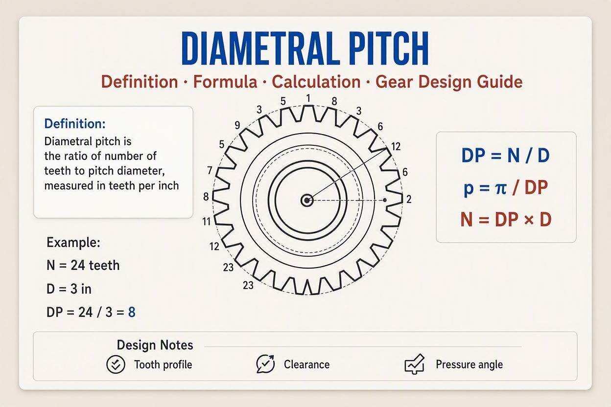
Diametral pitch (DP) is one of the fundamental measurements used to describe the size of teeth on an involute gear.
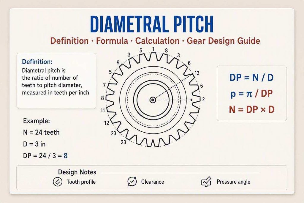
It tells you how many gear teeth are present for every inch of the gear’s pitch diameter. Unlike simply counting the number of teeth, diametral pitch gives engineers a standardized way to describe how large or small those teeth are. A gear with a higher diametral pitch has more teeth packed into a given pitch diameter, meaning its individual teeth are smaller. A lower diametral pitch produces larger teeth and is commonly associated with gears designed to handle greater loads where a heavier tooth form is desirable.
The concept becomes much easier when you imagine two gears sitting next to each other. Suppose both gears have a pitch diameter of 4 inches. If one has a diametral pitch of 8, it has 32 teeth because 8 teeth occupy each inch of pitch diameter. If another has a diametral pitch of 16, it has 64 teeth over that same diameter. The second gear therefore has teeth that are considerably smaller. This relationship is why diametral pitch is important in gear design, manufacturing, inspection, and replacement. When selecting a mating gear, the pitch system, pressure angle, tooth profile, and other specifications must be compatible; simply choosing gears with the same outside diameter is not enough.
Understanding Teeth and Pitch Diameter
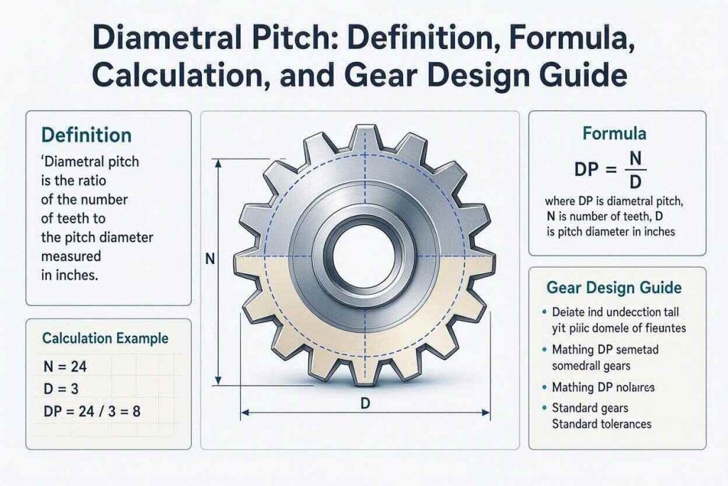
The basic relationship behind diametral pitch is straightforward: divide the number of teeth by the pitch diameter measured in inches. The pitch diameter is an imaginary reference circle used to define how two gears theoretically engage and transmit motion. It is not necessarily the same as the outside diameter that you can physically measure across the gear’s tips.
For example, consider a gear with 40 teeth and a pitch diameter of 5 inches. Its diametral pitch is 8 DP because 40 divided by 5 equals 8. If the same 40-tooth gear were designed around a 10-inch pitch diameter, its diametral pitch would be 4 DP. The teeth on the 4-DP gear would be substantially larger than those on the 8-DP gear. This simple calculation demonstrates why DP is useful: it connects tooth count and gear diameter into one standardized measurement.
Diametral Pitch Formula
The standard formula for diametral pitch is:
DP = N / D
Where:
- DP = diametral pitch
- N = number of teeth
- D = pitch diameter in inches
The formula is particularly useful when designing or checking spur gears, helical gears, bevel gears, and other gear systems that use the inch-based diametral-pitch system. For example, a gear containing 48 teeth with a pitch diameter of 6 inches has a diametral pitch of:
DP = 48 / 6 = 8
Therefore, the gear is an 8-DP gear.
The inverse relationship is equally important. If you already know the number of teeth and diametral pitch, you can determine pitch diameter:
D = N / DP
A 60-tooth gear with a diametral pitch of 10 therefore has a pitch diameter of 6 inches. This relationship is used repeatedly during gear design because changing either tooth count or pitch changes the resulting geometry. Engineers can use the equations to establish compatible gear dimensions before manufacturing begins, reducing the chance of selecting incompatible components.
How to Calculate Diametral Pitch
Calculating diametral pitch requires only two pieces of information: tooth count and pitch diameter in inches. Count the teeth carefully, determine the pitch diameter from the design drawing or gear specification, and divide the tooth count by the pitch diameter.
For example, imagine a gear has 72 teeth and a pitch diameter of 9 inches:
DP = 72 / 9 = 8
The result is 8 diametral pitch.
Now consider a smaller gear with 24 teeth and a pitch diameter of 3 inches:
DP = 24 / 3 = 8
Both gears use the same diametral pitch even though one is substantially larger. This is an important point: diametral pitch describes tooth size rather than simply describing the physical size of the complete gear. Two gears can have dramatically different diameters and tooth counts while still being compatible within the same pitch system.
Diametral Pitch vs Circular Pitch
Circular pitch and diametral pitch describe related aspects of gear tooth spacing, but they are not the same measurement. Circular pitch is the distance along the pitch circle from one corresponding point on a tooth to the same point on the next tooth. Diametral pitch, by contrast, represents the number of teeth per inch of pitch diameter.
The relationship between them is:
p = π / P
Where:
- p = circular pitch
- P = diametral pitch
For an 8-DP gear, the circular pitch is approximately:
p = π / 8 ≈ 0.3927 inches
This means the distance around the pitch circle associated with each tooth and space is approximately 0.3927 inches under the standard relationship.
The distinction matters because gear drawings and manufacturing specifications may use either measurement. If a design calls for a particular DP, substituting a gear based only on circular pitch without converting the values can create dimensional errors. Both measurements describe the same fundamental tooth-spacing relationship from different directions.
Diametral Pitch vs Module
One of the most important distinctions in gear engineering is the difference between diametral pitch and module. Diametral pitch is predominantly associated with the inch-based gear system, while module is the standard metric way of expressing tooth size.
Module is calculated using:
m = d / N
where m is module in millimetres per tooth when the pitch diameter is expressed in millimetres.
Because one system uses inches and the other uses millimetres, the conversion requires the appropriate unit relationship. The standard conversion between diametral pitch and module is:
m = 25.4 / DP
Conversely:
DP = 25.4 / m
For example, a 10-DP gear corresponds to a module of:
m = 25.4 / 10 = 2.54 mm
Likewise, a module 2 gear corresponds to:
DP = 25.4 / 2 = 12.7
In real engineering work, the distinction is more than a mathematical curiosity. Gear components should be specified within a consistent system because tooth dimensions, manufacturing tooling, center distances, and mating geometry all depend on the selected pitch standard.
Converting Diametral Pitch to Module
The conversion formula is useful when working with international engineering drawings or equipment that combines metric and imperial specifications.
| Diametral Pitch | Approximate Module |
|---|---|
| 4 DP | 6.350 mm |
| 5 DP | 5.080 mm |
| 6 DP | 4.233 mm |
| 8 DP | 3.175 mm |
| 10 DP | 2.540 mm |
| 12 DP | 2.117 mm |
| 16 DP | 1.588 mm |
| 20 DP | 1.270 mm |
| 24 DP | 1.058 mm |
| 32 DP | 0.794 mm |
The table demonstrates the inverse relationship clearly. As diametral pitch increases, module decreases. In practical terms, higher DP means smaller teeth, while lower DP means larger teeth.
Common Diametral Pitch Values
There is no single diametral pitch that is suitable for every application. Gear designers select a pitch according to factors such as load, speed, available space, manufacturing requirements, noise, strength, and the desired gear ratio.
Common values include 4, 5, 6, 8, 10, 12, 16, 20, 24, and 32 DP, although many other standardized values and special specifications are used in industry. Coarser pitches such as 4 or 6 DP produce relatively large teeth. Finer pitches such as 20 or 32 DP produce smaller teeth and can be useful where compact gearing and precise motion are important.
A useful way to think about the numbers is to treat DP as a packing density. A low number means fewer, larger teeth fit around a given pitch diameter. A high number means many smaller teeth fit into that same diameter. This makes DP especially useful when comparing gears that must occupy a limited amount of space.
How Diametral Pitch Affects Gear Size
Diametral pitch directly influences tooth dimensions and overall gear geometry. If tooth count stays constant, increasing DP decreases the pitch diameter. The relationship is:
D = N / DP
Suppose a gear has 40 teeth. At 8 DP, its pitch diameter is:
D = 40 / 8 = 5 inches
At 16 DP:
D = 40 / 16 = 2.5 inches
The tooth count has not changed, but the gear has become much smaller because the teeth are finer.
This characteristic can be valuable when engineers need to fit a gear train into a compact housing. However, smaller teeth are not automatically better. Tooth strength depends on the complete gear geometry, material, face width, heat treatment, loading conditions, lubrication, operating speed, and other design factors. A designer should therefore avoid selecting DP solely because it produces a smaller component.
Fine-Pitch and Coarse-Pitch Gears
The terms fine pitch and coarse pitch describe the relative size and spacing of gear teeth. A coarse-pitch gear has a lower DP and therefore larger teeth. A fine-pitch gear has a higher DP and smaller teeth.
Coarse gears can be advantageous in applications where substantial loads or rugged operating conditions demand robust tooth geometry. Fine gears can provide more teeth around the circumference and can be useful where compact dimensions, smoother engagement, and precise positioning are priorities.
There is a trade-off. Smaller teeth have less material in each tooth section and can be more sensitive to excessive loads, manufacturing errors, contamination, or damage. Larger teeth occupy more physical space but can provide a more substantial tooth form. Good gear design is therefore an exercise in balancing strength, size, speed, accuracy, and operating conditions rather than simply maximizing or minimizing DP.
How to Calculate Gear Dimensions Using Diametral Pitch
Once diametral pitch is known, several important gear dimensions can be estimated or calculated. The most fundamental relationship remains:
Pitch diameter = Number of teeth / Diametral pitch
Suppose you need a 48-tooth gear using 12 DP:
D = 48 / 12 = 4 inches
The pitch diameter is therefore 4 inches.
If the gear must mesh with a 24-tooth gear using the same 12-DP system, the second pitch diameter is:
D = 24 / 12 = 2 inches
The two gears therefore have pitch diameters of 4 and 2 inches. Their tooth counts are in the same 2:1 ratio, so the theoretical speed ratio is also 2:1.
Calculating Pitch Diameter
Pitch diameter is one of the most important dimensions in a gear train because it determines the theoretical rolling relationship between mating gears.
The equation can be rearranged depending on the information available:
D = N / DP
or:
N = D × DP
For example, if a design requires a 6-inch pitch diameter gear at 8 DP:
N = 6 × 8 = 48 teeth
This provides a direct way to determine tooth count from a desired gear diameter.
If a designer instead knows the required tooth count and pitch, the pitch diameter can be calculated immediately. This makes DP useful during preliminary design because engineers can rapidly test different combinations before moving into detailed CAD modeling and strength analysis.
Diametral Pitch and Gear Ratio
Gear ratio describes the relationship between the rotational speeds or tooth counts of two mating gears. For a simple gear pair, the ratio can be calculated using:
Gear ratio = Driven gear teeth / Driving gear teeth
Suppose an 80-tooth gear is driven by a 20-tooth pinion:
80 / 20 = 4:1
The driven gear therefore rotates at one-quarter of the speed of the driving gear, ignoring losses and other real-world effects.
Diametral pitch matters because mating gears need compatible tooth geometry. Two gears can have different tooth counts and different physical diameters while sharing the same DP. This allows designers to create different ratios without changing the fundamental tooth-size standard.
For example, a 20-tooth 10-DP pinion has a pitch diameter of 2 inches. An 80-tooth 10-DP gear has a pitch diameter of 8 inches. Their tooth counts give a 4:1 ratio, while the common 10-DP specification allows their teeth to mesh correctly under compatible gear standards.
Choosing the Right Diametral Pitch
Choosing a diametral pitch is not simply a matter of selecting the smallest or largest available number. The correct value depends on the application’s mechanical requirements. Engineers typically consider transmitted torque, rotational speed, center distance, gear diameter, available space, tooth strength, manufacturing capability, noise requirements, lubrication, service conditions, and required design life.
A compact mechanism may benefit from a finer pitch because more teeth can fit within a relatively small diameter. A heavily loaded industrial transmission may require a coarser tooth form or a more substantial gear design. High-speed applications can introduce additional concerns related to dynamic loads, vibration, tooth accuracy, lubrication, and noise.
The mating gears must also be designed as a system. Matching DP alone does not guarantee successful operation. Pressure angle, tooth form, helix angle where applicable, backlash, center distance, material, and manufacturing accuracy can all influence whether two gears work correctly together. This is why replacing a damaged gear by counting teeth alone is risky.
Why Diametral Pitch Matters in Gear Manufacturing
Diametral pitch provides manufacturers with a standardized way to define tooth size. Gear cutting tools, hobs, inspection equipment, and design software can all use pitch specifications to establish the required tooth geometry.
If a drawing specifies an 8-DP gear, the manufacturer has a fundamental tooth-size parameter from which the gear geometry can be developed. Other information is still required, such as tooth count, pressure angle, face width, material, heat treatment, bore dimensions, keyway details, and tolerances.
This standardization also helps when sourcing replacement components. Instead of relying solely on physical measurements, an engineer can identify the gear’s pitch system and compare it with manufacturer specifications. That reduces the likelihood of purchasing a visually similar component that does not actually mesh correctly.
Advantages and Limitations of Diametral Pitch
Diametral pitch has several practical advantages. It provides a compact way to describe tooth size, simplifies gear calculations, and integrates naturally with traditional inch-based engineering systems. It is also particularly useful when designing gear pairs because the relationship between tooth count and pitch diameter is direct.
However, DP has limitations. It belongs to an imperial measurement framework, so metric projects often use module instead. DP also does not completely describe a gear. Two gears with the same DP can still be incompatible if other parameters differ. Pressure angle, tooth profile, helix angle, backlash, and other specifications must be considered before gears are paired.
The correct mindset is to treat diametral pitch as one critical piece of a larger gear specification. It tells you about tooth size, but it does not tell you everything about how the gear will perform.
Conclusion
Diametral pitch is a fundamental gear-design measurement that expresses the number of teeth per inch of pitch diameter. Its basic formula, DP = N / D, makes it easy to calculate from tooth count and pitch diameter, while the rearranged equation D = N / DP helps engineers determine gear dimensions during design.
The relationship is simple but powerful: higher diametral pitch means smaller teeth, while lower diametral pitch means larger teeth. Diametral pitch also has a direct relationship with circular pitch and module, making conversions possible when working between imperial and metric engineering systems.
Understanding DP is essential when designing, selecting, inspecting, or replacing gears. But DP should never be considered in isolation. A properly matched gear pair also requires compatible tooth geometry, pressure angle, center distance, and other design specifications. Once these relationships are understood, gear calculations become much more predictable and gear selection becomes far less dependent on guesswork.
FAQs About Diametral Pitch
1. What does diametral pitch mean?
Diametral pitch indicates the number of teeth a gear has per inch of pitch diameter. It is calculated by dividing the number of teeth by the pitch diameter in inches. A higher DP represents smaller teeth, while a lower DP represents larger teeth.
2. What is the formula for diametral pitch?
The primary formula is DP = N / D, where N represents the number of teeth and D represents pitch diameter in inches. For example, a 40-tooth gear with a 5-inch pitch diameter has an 8-DP pitch.
3. Is a higher diametral pitch better?
Not necessarily. Higher DP creates smaller teeth and can allow a gear to be more compact, but tooth strength and load capacity depend on many other design factors. The appropriate pitch depends on the application, loading, speed, space, materials, and required service life.
4. What is the difference between diametral pitch and module?
Diametral pitch is primarily used in inch-based gear specifications, while module is used in metric gear systems. They have an inverse relationship: module = 25.4 / DP. Therefore, increasing DP corresponds to decreasing module.
5. Can two gears with different diametral pitches mesh?
Standard gears with different diametral pitches generally should not be directly meshed because their tooth sizes and spacing are incompatible. Properly mating gears normally need compatible pitch specifications along with compatible pressure angles and tooth geometry.